Orthopedic Appliances
Historical document, translated for reference. It reflects medical knowledge of the 1920s–30s and is not medical advice.
Summary
Orthopedic appliances are mechanical devices used to treat orthopedic conditions. This article describes their historical development, classification, manufacturing techniques, and various types including corsets and joint mechanisms.
Encyclopedia article (1928–1936)
Orthopedic Appliances, mechanical devices for the treatment of orthopedic diseases. The widespread use of mechanical principles in the treatment of orthopedic diseases led to the application of orthopedic appliances as early as ancient times. Already in 210 A.D., Caelius Aurelianus first described splints for paralysis. A. Pare (1501) in France and simultaneously Arceus in Spain proposed rather complex orthopedic appliances for the treatment of clubfoot. Fabricius of Aquapendente (1619) used a universal iron corset resembling knightly armor for the treatment of various deformities. In 1660, Glisson's work was published describing a series of supporting appliances, of which his loop is still widely used today. Le Vacher (1772) elaborates in detail on mechanical methods for treating rachitic curvatures and proposes a 'jury-mast'. Venel (1780) invented a bed for traction and a shoe for clubfoot, the further improvement of which was made by the Italian Scarpa (1803). Further mention should be made of Heine (1812), who, being a convinced advocate of the exclusive use of mechanics in orthopedics, contributed greatly to the widespread use of numerous types of orthopedic appliances, but at the same time earned criticism that because of him orthopedics fell into the hands of instrument makers. The introduction of gymnastic methods of treatment into orthopedics led to the formation of two extreme camps - adherents of dynamic and mechanical treatment, who were reconciled by Guerin and Bouvier (1837) in France and Berend (1861) in Germany, who developed specific indications for the use of various methods. In 1857, Delacroix proposed to replace the functions of paralyzed muscles with elastic traction. Mention should also be made of Hessing (1870), son of a poor potter, a self-taught man who invented appliances (see Hessing's appliance) that make it possible to use the limb in joint diseases. The era of Lister is characterized by the flourishing of surgical orthopedics, which significantly limited the excessive enthusiasm for orthopedic appliances and transformed apparatus therapy from a dominant basic method to an auxiliary one. Further accumulation of experience in the use of orthopedic appliances led to a reduction in their large number, which now have only historical interest, and contributed greatly to the improvement of the main types of orthopedic appliances, which in their various modifications are used at certain stages of treatment for almost all orthopedic diseases. All orthopedic appliances can be divided into 3 groups according to their purpose: 1. Fixing or unloading orthopedic appliances, which aim to hold the trunk or limbs in a certain position or relieve them of load. 2. Reducing orthopedic appliances, which restore the lost normal shape to the limbs or trunk by traction or pressure. 3. Replacing orthopedic appliances - to replace the function of paralyzed muscle groups or to replace a limb defect; in the latter case, they are called prostheses (see). Orthopedic appliances can be portable, when the patient wears them on himself, or bed-type, when their use requires staying in bed; in such cases, the points of application of forces, in addition to the patient's body, are also outside it.
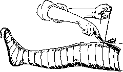
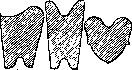
The main requirements for orthopedic appliances are as follows: precise fit, simplicity of design, low cost, durability, and lightness. While yielding to plaster casts in accuracy of modeling, accessibility, and low cost, orthopedic appliances have the advantage of being lightweight, and above all, removable, which is important for observation and carrying out therapeutic procedures. As a rule, orthopedic appliances are made of leather, less often of fabric, and reinforced with metal splints. A substitute for leather can be fabric (knitwear, canvas) impregnated with glue, gelatin, emadetine, etc. Orthopedic appliances should be made individually from special plaster models. The model is obtained as follows: the required part of the body is smeared with vaseline, lard, or some oil, then along the midline of the trunk or limb a strong cord or wire is pulled, and over it circular turns of plaster bandage are applied in 2-3 layers. The plaster cast should be carefully modeled according to bony protrusions. Without letting the cast dry completely, the end of the cord is pulled, as a result of which a longitudinal ridge rises on it, along which the cast is cut (fig. 1). After minimally separating the edges of the cast, it is removed and immediately the edges are brought together again, securing the cast with several turns of gauze bandage. After the negative cast dries, its inner surface is smeared with some fat (Fridland recommends a solution: one stearin candle per 400.0 kerosene) and filled with plaster paste or gypsum (cheaper). After the negative is removed, the positive is opened, which accurately reproduces the shape of the trunk or limb. Subsequently, the positive undergoes additional correction - in those areas where pressure needs to be achieved, a more or less thick layer of plaster is removed, and conversely, on those areas that need to be relieved of pressure (iliac crests, condyles, etc.), a layer of plaster should be applied. Then the manufacture of the leather sheath from calfskin or cowhide begins, which is cut according to a paper 'pattern' (fig. 2), previously made from the model. The leather is first soaked and hardened in a solution of glue or potassium bichromate, and before use it is soaked in warm water and stretched on the model, where it is fixed with small nails. For greater strength or to connect several sheaths into one, metal splints are fitted on the model itself, placed in a known direction according to the laws of mechanics. Subsequently, the sheath is removed from the model, fastened with rivets to the splints, padded inside with flannel or suede, and equipped with lacing.
Figure 2. Patterns for cutting sheaths: a-hip; b-leg; c-foot.
For movable connection of splints, the ends participating in the joint are processed in the form of
Figure 3. Hinge constructions: 1-overlay; 2-fork-shaped or through; 3-block-shaped (brake shoulders are indicated by dotted lines); 4-petal. These hinges allow movement in only one plane, where movement in several planes is necessary, either a ball joint or a combination of the two aforementioned hinges with mutually perpendicular axes of movement (fig. 4 and 5) are used. To
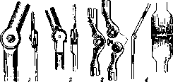
Figure 4.
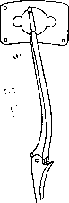
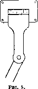
Figure 4. Combined hinge for rotation with abduction. Figure 5. Combined hinge for flexion with abduction. obtain a greater range of motion, Stillman combines three overlay hinges, any of which can be
Figure 6. Triple hinge of Stillman with key.
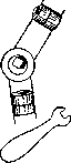
Figure 7. Schematic drawings of splints: a-sector splint of Stillman for gradual redressation; b-sector splint of Braatz for straightening and stretching the knee joint; c-clamps for fixing the hinge.
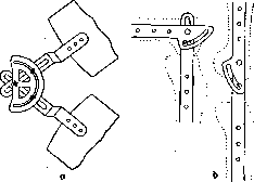
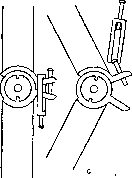
obtainable changes in the relative position of the splints participating in the hinge joint, sector splints of Stillman, Braatz, or a device in the form of clamps are used, the application of which is clear from fig. 7. For the purpose of locking the hinge for a certain period of time, 'locks' of various designs are used, which mainly consist of a latch fixed on one hinge, penetrating into the corresponding recess of the second hinge (fig. 8). Among the fixing orthopedic appliances, the corset is most widely used. Its task is the immobilization and unloading of the affected part of the spine. Immobilization of the spine is achieved by precise fitting of the corset, which at the bottom covers the pelvic girdle, and at the top is fixed with the help of crutches on the shoulder girdle (see Corsets, Volume XIV, article 20, figure 6). Unloading of the spine is achieved by transferring the weight of the body through crutches located in the axillary fossae, and vertical metal splints fixed to them directly to the pelvis. The main splints in the corset are arranged as follows: the upper semicircle along the upper edge of the corset (behind and on the sides), the lower circular splint (buckle)-one finger above and parallel to the crista ossis ilii. On both sides along the middle axillary line, vertical splints are fixed, at the bottom resting against the lower pelvic splint, at the top connected to the upper semicircle and ending with crutches. When taking measurements for a corset for tuberculosis of the spine, the latter is reclined (lordosed), as a result of which the affected vertebral bodies are unloaded due to the transfer of the main load to their arches. Reclination is achieved by suspension using Glisson's loop and
with a key (Fig. 6). Brake devices in the form of small shoulders on hinges (Fig. 3, 3) serve to limit the range of motion. For gradual, periodic - with simultaneous abduction of the lower extremities posteriorly beyond the frontal plane. Usually, the corset is made of leather or of the aforementioned surrogates thereof and for better Figure 8. Schematic drawing of a lock for fixing the hinge in the extended state. perspiration is provided with numerous holes. In cases requiring less strict immobilization, cloth corsets can be used, and when there is no need for unloading, equipping the corset with crutches is superfluous. In lesions of the cervical spine, the so-called "jury-mast" spare mast proposed by Levasseur has long been used, which is now replaced by a more convenient and less ugly collar (see vol. XIV, p. 19, Fig. 3 and 4). Supporting the head in the chin and occipital regions, it transfers its weight entirely to the shoulder girdle. An symmetrically constructed collar is used for torticollis. The next in frequency of distribution among orthopedic appliances are tutores, intended for joint immobilization and fixation of limbs along their length. They are splint-and-shell appliances without hinges, which distinguishes them from other fixation devices. For immobilization of the hip joint, a tutor is used, consisting of a high belt-semicorset extending into a shell enclosing the thigh (Fig. 9). The tutor for the knee joint is a conical shell supported by lateral splints, beginning from the inguinal fold and ending above the ankles (Fig. 10 a). A stirrup attached to the lower end of the tutor, or a narrow pelvic belt fastened to the upper end, prevents the tutor from slipping. Tutores for the ankle and elbow joints are shown in Fig. 10 (b and c). The remaining orthopedic appliances are splint-and-shell devices equipped with hinges at the level of the joints, and are used both for fixing limb segments in a certain position while simultaneously preserving movements in the joints, and for limiting lateral movements in flail joints. A typical example of them is the Hessing apparatus (see Hessing apparatus). A complete fixation apparatus for the lower extremity consists of femoral and tibial shells, as well as a shoe for the foot, connected to each other usually by overlapping hinges. Often, for better fixation of the apparatus, a narrow pelvic belt is also used, articulating with the upper edge of the outer femoral splint by means of a double hinge, which increases the range of motion in the hip joint. In case of flailness of a single hip joint, one can be limited only to the femoral shell, but the pelvic belt must be significantly wider. The apparatus for flailness of the knee joint consists of femoral and tibial shells, and the boot used for the ankle joint consists of the tibial shell and a shoe.--A complete fixation apparatus for the upper extremity consists of 4 parts: a shell enclosing the shoulder girdle, and shells for the arm, forearm, and hand with lateral splints articulating at the level of the joints with overlapping hinges. To connect the arm to the shoulder girdle, a ball-and-socket hinge or a combination of a double hinge is used. Just as on the lower extremity, in case of flailness of any joint of the upper extremity, the fixation apparatus as a rule consists of two shells enclosing the segments of the limb located above and below. Very frequently, locks are used in fixation apparatuses, especially in the knee joint, which is locked during walking, and in the elbow joint, which is fixed by a lock in flexion at an angle of 85°, which makes the upper extremity functionally more usable. Using Stillemann's sector splint, the elbow joint can be fixed at any angle.-- The apparatus against habitual dislocation of the shoulder joint consists of a shell tightly enclosing the corresponding shoulder girdle and fixed on it by 1 or 2 straps passing under the armpit of the healthy side. A second shell enclosing the shoulder articulates with this shell by means of hinges allowing the arm to be raised only to the horizontal plane, which prevents recurrences of dislocations (Fig. 11). For habitual dislocation of the kneecap, Haudek proposed a leather band
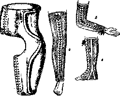
Figure 9.
Figure 10.
Figure 9. Tutor for immobilization of the hip joint or the so-called "spine". Figure 10. Tutores: a - for the knee joint; b - for the elbow joint; c - for the ankle joint.
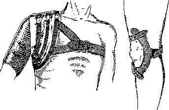
age in the form of a half-ring enclosing the kneecap from the outside (Fig. 12). The introduction of the principle of unloading into fixation apparatuses for the lower extremity belongs to Thomas. Unloading is carried out with the help of a seat fixed on the upper end of the lateral splints of the apparatus, the length of which exceeds the length of the limb by 1-2 cm. When stepping on the limb in such an apparatus, the entire weight through the ischial tuberosity and perineum is transmitted to the seat, and from the latter through the lateral splints to the metal sole of the apparatus, while the limb hangs freely in the apparatus, not reaching the bottom of it by the indicated 1-2 cm (Fig. 13). By using such an apparatus, unloading of the affected joint is achieved while walking, and by locking the hinge, its immobilization is achieved, with the simultaneous function of the remaining healthy joints of the limb. Reduction apparatuses carry out their correcting action using the force of a spring, lever, elastic traction or finally body weight. In scoliosis in growing patients, it is possible
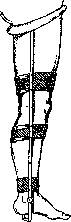
Figure 11. Fixation apparatus for habitual dislocation in the shoulder joint.
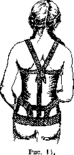
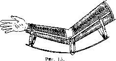
Figure 12. Haudek's fixation bandage for habitual dislocation of the kneecap (outer).
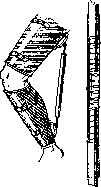
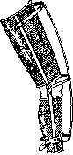
Figure 13. Apparatuses for immobilization and unloading of the knee joint: a - more expensive model; b - simplified model.
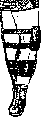
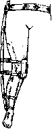
Figure 16.
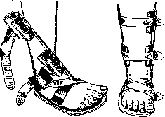
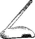
Figure 17. Figure 19.
to achieve a certain reduction of the rib hump by using a pressure pad in the area of protrusion. In the corset, corresponding to the apex of the rib hump, an oval opening is cut out, filled with a pad (a metal plate padded with felt), over which a steel plate with a screw passing through it is thrown, the rotation of which regulates the degree of pressure.-In the treatment of stooping, roundness of the back, so-called straight-holders are used. Nyrop's straight-holder consists of a steel belt padded with soft material, worn around the pelvis and fixed by two arcs passing through the iliac crests. From the middle of the belt posteriorly, a metal plate rises upwards along the spine, to which at the level of the armpits a horizontal half-ring is riveted, reaching laterally to the anterior axillary lines and ending in steel tongues. From the latter, straps begin, Lorenz's plaster bed, used for spinal deformations (see Plaster bandages, corsets, little beds). In adults with spinal lesions, it is often possible to dispense with a plaster bed by using a wooden flat
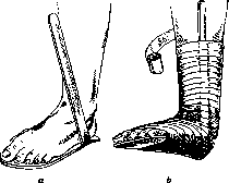
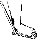
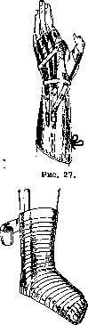
Figure 20.
Fig. 21. Splint for the correction of pes equino-varus congenitus.
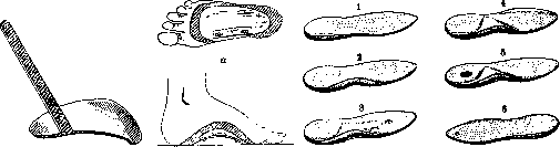
Figure 22. Splint for the correction of pes equino-varus congenitus: a - application; b - bandaging.
Figure 25. Metal spring insole supporting the arch of the foot: a - from below; b - from the inside. Figure 26. Types of insoles: 1 - supinator raising the inner edge of the heel; 2 - the same, and supporting the arch of the foot; 3 - the same with a Seitz pad and a recess for a callus; 4 - the same as 2, but with simultaneous raising of the outer edge in the forefoot; 5 - the same as 2, but with a recess under the calcaneal spur; 6 - pronator raising the outer edge of the heel and middle section.
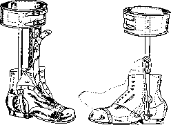
Figure 28.
Figure 29.
degrees of flatfoot, the supinator insole raises only its inner edge under the heel (Figure 26, 2); in more advanced cases, the arch of the foot is also filled (Figure 26, 2). With the simultaneous presence of transverse flatfoot, a pad is used that raises the middle metatarsal bones, and a recess is made for a painful callus (Figure 26, 3). When, to correct the position of the heel, it is necessary to raise its inner edge by more than 11/2 cm, and the foot acquires a tendency to slip outward from the insole, then to hold it up
Sh I" from the calcaneal spur, de
\J; appropriate place rec
ession (Figure 26, 5). With
°„ Jp7 clubfoot, applies
I Jw I with the outer edge (Figure
J^ 26, 6), the so-called prona
Figure 30. plantar splint and a pad pressing on the dorsal surface of the flexed joint. Among substituting appliances, we must note only those that replace the function of paralyzed muscles. The active force in them is elastic traction or, less commonly, a spring. In paralysis of the flexors of the forearm, the splint-trough appliance is provided on the flexor surface with crossing rubber cords, which, upon active relaxation of the preserved function of the extensors, flex the hand at the elbow. In paralysis of the extensors of the fingers, the appliance (Figure 27) consists of a trough covering the forearm, wrist, and metacarpus, and five leather rings, one for each finger. Rubber cords running from the fingers along the dorsum replace the traction of the paralyzed flexors. On the lower extremity, in paralysis of the quadriceps muscle, its function is replaced by a strong rubber band (one or two) attached in a taut state to the anterior surface of the femoral and tibial troughs of the fixation appliance. During walking, the rubber helps extend the knee joint, and at the moment of support on the foot, guarantees it against buckling. In paralysis of the muscle groups of the foot, a boot with side splints is used, ensuring the correct position of the foot. To eliminate foot drop in paralysis of the extensors, a rubber cord is passed under the tongue of the boot, fixed in the toe and fastening to a ring encircling the lower leg (Figure 28). For the same purpose, Goldschmidt uses a coil spring that sets the foot in a position of dorsiflexion (Figure 29). In weakness of the peroneal muscles, to eliminate clubfoot, a rubber cord is used, attached to the outer side of the forepart of the boot (Figure 30).
Already in the surgical kits of Hippocrates' time there were saws and chisels, and in his works "De fracturis" and "De articulis" he indicates how to treat various skeletal deformities by means of special devices. In the 16th century, many authors (H. v. Gersdorff, Fabricius ab Aquapendente, F. Hildanus, Ambroise Paré, and others) invented many different apparatuses for the correction of skeletal curvatures. Since then, there has been a gradual increase in the number and improvement of orthopedic appliances. Modern orthopedic appliances can be divided into the following groups: 1. General surgical instrumentation (see Surgical instrumentation) necessary for orthopedic operations. 2. Instruments used in orthopedic operations on tendons, muscles, nerves, and bones. 3. Orthopedic devices used for bloodless corrective interventions (redressement, osteoclasis, etc.). 4. Instrumentation for skeletal traction and plaster work (see Traction). I. Instruments for operations on muscles and tendons. For subcutaneous dissection of tendons, special tenotomes (knives) have been proposed. The Guerin tenotome (Figs. 9 and 10), straight or curved, blunt-ended, is used for dissecting tendons from the outside inward. The blunt-ended, short Hübscher tenotome (Fig. 5) has a spear-shaped blade at the other end of the handle for puncturing the skin. For dissection in the direction from the depth outward, the sharp-pointed, curved Dieffenbach tenotome with a short blade (Fig. 7) is convenient. The Vulpius tenotome (Fig. 8) is intended for more deeply situated tendons; it has a short curved blade on a long, rounded neck. The sharp-pointed Riedinger hook (Fig. 6) serves for lifting and tensioning the tendon, mainly during subcutaneous tenotomies. Suturing of tendons is performed with non-cutting round needles, curved in an arc along their length ("intestinal" needle). Shortening of tendons can be done with the help of the Becker tenoplicator (Fig. 4). The tendon clamped by the tenoplicator forms folds and is sutured with a straight needle. When transplanting tendons, the Codivilla clamp (Fig. 6) is used for the suture. For the formation of a channel in the subcutaneous tissue or muscles when passing a tendon through it, a standard sponge forceps, the Lange clamp (Figs. 12 and 13), the Besalski claw clamp (Fig. 14), and the Codivilla elastic probe (Fig. 61a) are commonly used.
II. For operations on nerves, instruments (scalpels, scissors, forceps, clamps) must be distinguished by great precision due to the delicacy of the tissue. Scalpels (Figs. 18-20) of various lengths have been proposed. Forceps (Figs. 16 and 17), anatomical and surgical, must be well-fitted. Scissors (straight or curved) are used sharp-pointed, and to avoid damaging them, it is recommended to cut only nerve tissue with them. Fig. 15 shows the Spitzy forceps for grasping nerves; the lumen resulting from compressing the forceps must correspond to the thickness of the nerve trunk in order to protect the nerve from trauma. With a thick perineurium, one can use thin, small clamps with sharply tapered ends (Fig. 37) for grasping it. For moving and passing a nerve through tissues, a special instrument proposed by Spitzy (Fig. 25) is used, consisting of a hollow tube. The tube is passed through the tissues in the desired direction, and the nerve is pulled through it. A sterilizable electrode necessary for certain orthopedic operations was proposed by Stoffel (Fig. 24). During the operation, the electrode hangs on a stand (Fig. 21) above the surgeon's head and can be lowered at the necessary moment.
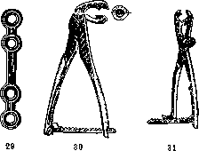
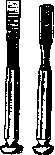
III. For osteotomy, one of the most frequent orthopedic operations, a multitude of chisels and osteotomes have been proposed. Figure 53 depicts a chisel of simple form; Figs. 32 and 33 show the Bergmann chisel (12, 15, and 20 mm in width), the blade of which passes directly into the handle. A very convenient osteotome was proposed by Mac Ewen (Fig. 34). It has an octagonal handle and an enlarged platform for striking with a mallet. On the narrow edge of the blade, there are graduations, which allows one to monitor the depth of the osteotome's penetration into the bone; the blade width is 9, 11, and 15 mm. Fig. 35 shows the same osteotome, but of a gouge-like form. The Gocht chisel, made from a solid strip of steel (Fig. 23), is practical; the handle is inconvenient for holding, but it allows for control of the blade's direction. For subcutaneous
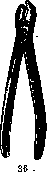
34 35
40 41
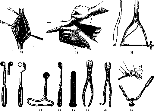
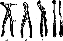
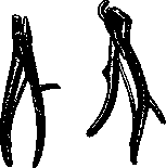
For osteotomies, the chisel proposed by Lorenz (Lo-renz; fig. 3) is used. Its length is 17 cm, handle 10 cm, width of blade 1 cm. 'Elevators' and 'protectors' (Schiitzer) greatly facilitate the performance of osteotomies. By fixing the bone, they push aside soft tissues, protect them from the blade, and reduce bleeding from soft tissues by tissue tension. In Vol. XIV (p. 169), fig. 9 shows the Lange elevator. For femoral osteotomy according to Schantz (palliative operation for congenital dislocation of the hip in adults), steel screws are used, which are screwed into the bone before its incision (fig. 70). With the help of screws, the angle between bone fragments can be controlled, which is important in this operation (fig. 71). On the free end of the screw there is a face for placing a key, by means of which the screw is screwed into the bone. After the operation, the screws are immobilized in the cast until the consolidation of bone fragments begins, therefore they must be made of stainless steel. Bone suture can be performed besides wire with the help of metal plates of various lengths according to Leno (fig. 29), aluminum plates (fig. 28), celluloid plates according to Lange, or metal staples (Vol. XIV, p. 126, fig. 5). The plates are fixed with screws. For connecting bones, metal nails or pins made of ivory or ox bone are also used. Bone fixation is performed with the simplest bone forceps of Langenbeck (fig. 45), Ollier (fig. 46) or more complex but more convenient forceps, for example, of the Lambotte type (Lambotte) (fig. 30, 31), which allow to firmly fix the bone by means of a lock. Franke proposed a clamp (fig. 63) for holding bone fragments until the hardening of the plaster cast, which allows to do without bone suture. For laminectomy, many models of forceps have been proposed, for example, forceps of Hoffmann (Hoffmann; fig. 54), Kerven (Quervain; fig. 55), sharp ones according to Horsley (Horsley; fig. 50). The 'crocodiles' of the Lannelongue type (Lannelongue; fig. 49) or simple forceps of Luer (fig. 11) are also convenient. Krause's laminectomy is shown in fig. 48. Operations on joints sometimes require special instruments. For smoothing rough bone surfaces, files according to Scheppelmann (fig. 50 and 51) are used. For scraping cartilage from the acetabulum during arthrodesis, Lorenz proposed a special sharp spoon (fig. 40). A somewhat different appearance has the spoon for the same purpose according to Hoffa (Hoffa; fig. 41). For deepening the acetabulum, Hoffa proposed a short spoon (fig. 42), and Doyen - a special drill (fig. 44). For the bloodless reduction of hip dislocation, Codivilla uses a lever, the action of which is clear from fig. 69. For expanding the joint capsule during reduction of hip dislocation, Calot proposed a 'subcutaneous' dilator (fig. 39, 67). For operations on the formation of the hip joint, Murphy proposed a round milling cutter and a concave file in the shape of a hemisphere (fig. 59). IV. Equipment for bloodless orthopedic operations. The simplest device is a loop, used for the redressation of certain types of clubfoot. Very simple and convenient for redressation of clubfoot are the wooden wedge of König, covered with felt and oilcloth (leather) (fig. 38), and the apparatus of Schulze (fig. 73). The latter consists of two boards connected by a hinge. The leg is fixed in the apparatus with straps. For the treatment of clubfoot in children, what is listed is quite sufficient. For adults, many kinds of redressators have been proposed. Fig. 58 shows the 'Thomas wrench' - Thomas' osteoclast, which can also be used as a redressator. It is modified by Stille. Its 'claws' can come together (when gripping the limb) by a screw located in the handle. Fig. 74 shows the Stille redressator-osteoclast, fig. 74a shows redressation with the help of this apparatus, fig. 47 shows the Turner redressator, fig. 64 shows the Gocht redressator, fig. 22 shows the Phelps-Gocht osteoclast-redressator, fig. 78 shows it in action, fig. 75 shows the Lorenz-Stille osteoclast. The limb is fixed in it with a screw. Traction with a leather loop is also performed with a screw. Fig. 66 shows osteoclasis, and fig. 68 shows redressation by means of the Lorenz-Stille apparatus. As in any redressator, felt or rubber pads, sponges are used to protect the skin from damage. The Rizzoli osteoclast (Rizzoli; fig. 62) is very simple. The limb is held with rings, pressure is applied with a screw. For the treatment of clubfoot and flatfoot, the Schede redressator (fig. 79, 57, 65) and the Gorman redressator (fig. 60) have been proposed recently. The construction and action are clear from the figures. Extension tables, frames, etc., can also be included in the group of redressating appliances, which (especially recently) have been offered in many designs. The Abbott bed (fig. 26) is used for the correction of scoliosis in children before applying a plaster corset. For the correction of deformities of the spine, the Wullstein frame (Wullstein; fig. 27) is used, for the correction of the spine in kyphosis - the Schede table (fig. 72). Fig. 76 shows the Lorenz apparatus for redressation of contractures of the hip joint by screw traction. The healthy leg rests on a special stand, the knee is fixed. Fig. 77 shows an apparatus for redressation of contracture of the knee joint. For bloodless reduction of congenital dislocation of the hip joint, the 'Muskel-quetscher' of Gocht (fig. 1) is used, an instrument designed for lengthening the contracted adductor muscles of the thigh. It is placed transversely to the direction of the muscle fibers at their attachment to the pubic bone, after which sawing movements are made with it. The skin, rubbed with alcohol and covered with sterile gauze, should not be damaged at this time. Gocht also proposed levers (fig. 2) for fixing the pelvis during reduction. The method of use is indicated in fig. 56. Lit.-em. lit. to the article Orthopedics and Prostheses. V. Blokhin.
Related articles
Mentioned in
Cite this page
“Orthopedic Appliances.” Soviet Medical Encyclopedia. English translation of Bolshaya Meditsinskaya Entsiklopediya, 1st ed. (Moscow, 1928–1936), ed. N. A. Semashko. https://sovietmedicalencyclopedia.com/article/orthopedic-appliances/