Productivity
Historical document, translated for reference. It reflects medical knowledge of the 1920s–30s and is not medical advice.
Summary
This article contains a fragmented collection of entries, primarily focusing on the principles and mechanical methods of planimetry, including the use of Simpson's formula and Amsler polar planimeters for measuring areas in anthropometry. It also includes unrelated fragments regarding sanitary-educational posters.
Encyclopedia article (1928–1936)
PRODUCTIVITY
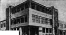
BATTLE FOR INDUSTRIALIZATION. Improve sanitary condition! Fig. 19. Fig. 20. Fig. 14-20. Sanitary-educational illustrated slogans. The first of them (fig. 14) is an example of a purely mechanical combination of text with a drawing, having no relation to it and being politically completely alien. Only two of the presented slogans (fig. 16 and 17) are relevant in content and politically sharpened. Figure 19 and 20 - posters on sanitary topics ('Quacks', 'Creche'). Fig. 16. Fig. 17. ... HOW TO RAISE A CHILD!
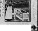
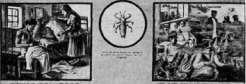
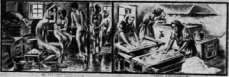
Fig. 21. Figure 22.
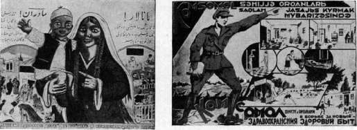
Figure 24. Figure 21-24. Sanitary-educational posters of national minorities.
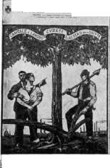
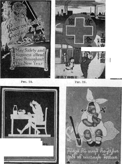
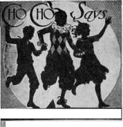
Figure 30. Fig. 25-32. Examples of foreign posters. In some, there is undisguised class bourgeois ideology, propaganda of class peace ['Capital and labor care for health!' (fig. 25), 'St. Peter' (fig. 27), 'Peace on earth' (fig. 28)], in others - a detachment from the real conditions of existence of the broad working masses ['Milk, vegetables and fruits' (fig. 31)] etc. Figure 31. Figure 32.
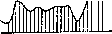
millimeter squares, fully included in the area of the measured figure; to them is added the number of all those squares, the greater part of the area of which (by eye) belongs to the measured figure; those squares which are occupied less than half are not counted. For not very small areas of measured figures, this method gives results that are quite satisfactory in accuracy. A more convenient and accurate technique consists in superimposing on the measured figure a grid of equidistant parallel lines (Figure 1), the lengths of which from edge to edge of the figure are measured with a compass, or, which amounts to the same thing, in drawing on the drawing itself a series of equidistant ordinates with subsequent measurement of them. If the lengths of all these ordinates from the first to the last are denoted by Y0, Y1, Y2, ..., Yn, then the area P will be expressed with very good accuracy by Simpson's formula:
Figure 1. P = [x/3] * [Y0 + Yn + 4(Y1 + Y3 + ... + Yn-1) + 2(Y2 + Y4 + ... + Yn-2)], where x is the distance between adjacent ordinates or grid lines. 2) The mechanical method of measuring areas is carried out with the help of planimeters. The most common type of planimeter is the Amsler polar planimeter. Its theory is quite complex and cannot be presented here, but the technique of working with it is as follows: the polar planimeter consists of two levers connected by a hinge: the pole lever P and the tracer lever A (Fig. 2).
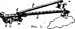
In a more perfect, so-called compensation model (depicted in Fig. 2), the hinge is replaced by a detachable ball joint H. The pole lever P has a needle at the free end, loaded with a weight b, and stuck fixedly somewhere in the plane of the measured figure; the tracer lever A also has a needle f at the free end, equipped with a handle s. On the other side of the hinge, a small wheel with a rim L is attached to the tracer lever, divided along the circumference into 100 parts. For greater accuracy of readings, a vernier K is attached to it. The number of full revolutions of the wheel L is counted by the disk m. To measure the area of a figure, the pole needle b is stuck somewhere inside the contour of the figure, at an arbitrarily chosen point, the needle f of the tracer lever is placed somewhere on the contour of the figure, and the readings of the counters L and m are recorded. Then, carefully trace the entire contour of the figure with the needle f in the direction of the clock hand (necessarily along a closed curve!) and return back to the starting point. During this operation, the wheel L rolls along the plane of the drawing; it is necessary to arrange the drawing and the pole needle b so that the wheel can roll quietly along the paper the whole time without sliding off it. Upon completion
of the full tracing, the readings of the counters are read again. The difference between the second and first readings gives a measure of the area of the figure in the scale indicated in the planimeter's passport. If such a passport is not available, then the scale can be determined as follows. Take a small ruler (usually attached to each planimeter), having a short needle at one end, and a very small depression at the other, located exactly 2, 4, or 6 cm from the needle. The needle of the ruler is stuck into the drawing board, and the needle f of the planimeter is placed in the depression, after which it is traced together with the ruler 10 times around the fixed needle of the latter, thus describing 10 regular circles of radius 2, 4, or 6 cm. The area
of such a circle is equal to 4π, 16π, or 36π cm2 respectively; if the reading on the planimeter after 10 tracings shows N divisions of the counter, then N = 10 * 4π cm2 (or 10 * 16π, or 10 * 36π), and consequently one division of the counter is equal to [N/10 * 4π] cm2.
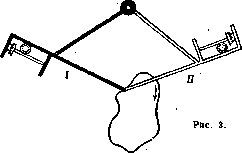
One can (although this gives less accuracy) trace a square with a side of 10 cm with the planimeter (by hand, and not along a ruler, the latter will be less accurate!); if the difference of the readings is M, then one division is equal to [100/M] cm2. Often planimeters are equipped with movable tracer levers, allowing the distance df to be changed. The scale of the planimeter changes in proportion to this distance: if df is reduced by half, then each division will express half the area: the planimeter will become twice as sensitive. If the length of df is denoted by R, the radius of the rolling rim of the wheel L by r, then the area of the measured figure P and the counter reading U are related by the equation P = 2πr * R * U. For greater accuracy, it is recommended a) to trace the figure several times and take the arithmetic mean of all results, b) not to set the counter to zero and generally not to touch it during work, but to read the initial and final readings, c) when working with a compensation planimeter, perform tracings without changing the position of the pole, first with one, then with the other arrangement of the tracer lever according to Fig. 3, and take the averages of both types of readings. The best polar planimeters are manufactured in Switzerland by Coradi (Zurich), and in Germany by Ott (Kempten). A polar planimeter of the described design is suitable only for measur-
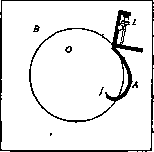
Fig. 4. ing areas from drawings; it cannot be used to measure the cross-sectional area of any body without sawing the latter. In view of the fact that the measurement of cross-sectional areas is of great interest for anthropometry (for example, the cross-sectional area of the chest, skull, pelvis, muscle masses, etc.), Ott currently manufactures, according to Bernstein's design, a modification of the polar planimeter, calculated precisely for such measurements. Such a planimeter consists of a board B (Fig. 4) with a round hole O, along the rim of which a tracer lever A of a curved shape rolls, having a point f at the end. The part of the body being studied is inserted into the hole of the board and fixed; the point f is traced around this part of the body, and then the reading of the wheel L gives a measure of the cross-sectional area according to the formula [P = 2πr * D * U], where D is the distance from the point f to the plane of the rim of the wheel L.
Related articles
Cite this page
“Productivity.” Soviet Medical Encyclopedia. English translation of Bolshaya Meditsinskaya Entsiklopediya, 1st ed. (Moscow, 1928–1936), ed. N. A. Semashko. https://sovietmedicalencyclopedia.com/article/productivity/