Aspirators
Historical document, translated for reference. It reflects medical knowledge of the 1920s–30s and is not medical advice.
Summary
This article describes the medical and laboratory use of aspirators, which are devices designed to suction fluids from body cavities or move gases through laboratory equipment using negative pressure. It details various historical models, including the Stintzing, Potain, and Bronner aspirators, as well as laboratory water-jet and reversible aspirators.
Encyclopedia article (1928–1936)
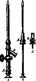
ASPIRATORS (from Latin aspirare - to inhale), apparatuses for suctioning fluids from body cavities by means of air rarefaction. They are used in clinical practice for diagnostic and therapeutic purposes, mainly for suctioning exudates and transudates of the pleural cavity. For a test puncture, suction is usually performed with a 5-10 cc syringe with a long and sufficiently thick needle to avoid breakage and to obtain viscous fluids, e.g., pus. For draining large quantities of fluid, a trocar is most often used, for example, Stintzing's (see Figure 1), with a rubber tube, about 0.5 cm in diameter and about 1 m long. The trocar is inserted into the intercostal space, and the rubber tube attached to it, previously filled with sterile water, is lowered into a measuring cylinder. A siphon is created, and the negative pressure in it will correspond to the column of liquid in the tube, equal to the distance from the chest to the floor (see Figure 2). This method of suction, in addition to the simplicity of the instrumentation, is the safest, because the pleural cavity is at all times under the same negative pressure. A significant disadvantage of the other aspirators is the fluctuating pressure, which especially applies to the Dieulafoy apparatus. Figure 1. Stintzing's trocar: 1-in folded state; 2-without cannula; 3-cross-section of the middle part; A-cannula handle; H-tap; S-discharge tube; G-trocar attachment.
In Furbringer's apparatus, suction is performed by mouth; in Bunsen's apparatus, air is rarefied by water flowing from one vessel to another. Some use a water-jet pump with a manometer. In practice, Potain's aspirator (the newest Stintzing model—see Figure 3) is most often used. In it, by means of a pump
B. Egorov.
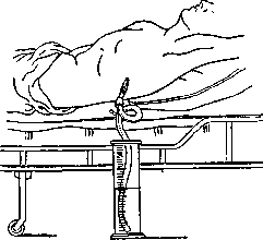
Figure 2.
or a rubber bulb, the air is rarefied in a measuring flask, into which fluid begins to flow as soon as communication is established between any body cavity and the interior of the apparatus flask by means of a trocar puncture.
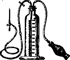
Figure 3. Stintzing's apparatus. Bronner's aspirator, an apparatus for treating chronic gonorrheal urethritis with passive hyperemia. Bronner's aspirator consists of a straight hollow bougie with numerous holes, equipped with a rubber bulb for rarefying the air in the bougie; when the bulb is compressed, the bougie,
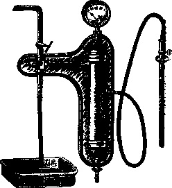
Figure 4. Bronner's aspirator.
inserted into the urethra, acts like a large number of small dry cups acting on the urethral mucosa. Later, to regulate the suction force, the Bronner aspirator bougie was connected, instead of a bulb, to a water pump equipped with a manometer (see Figure 4).
Laboratory aspirators, apparatuses capable of drawing air and gases into themselves or sucking them through vessels connected to such apparatuses. Aspirators are very commonly used in various works in chemical laboratories. The principle of their design is based on the following: a liquid (water, mercury) flowing out under the pressure of its own weight from the apparatus reduces the atmospheric pressure in the latter and, thereby, draws air (gases) into it from the place under study, which is connected to the apparatus by a tube. The most common type of laboratory aspirator is shown in Figure 5. A metal vessel A is filled to the top with water; its top communicates, by means of a tube t, with the place from which the gas is being sucked out. The lower tap L serves for releasing water.
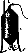
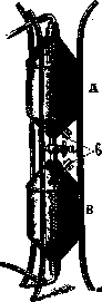
Figure 5.
Figure 6. If you open tap L and the tap at tube t, water will pour out of A, and gas will enter in its place through tube t; the volume of the flowed-out water will indicate the volume of gas that entered A. By means of tap R, the speed of water outflow and gas intake can be regulated. In a similar way, an ordinary laboratory glass bottle with a discharge tap (tubulus) placed at the bottom can be used; for this, the bottle is filled with water, a tight stopper with a glass tube is inserted into the neck of the bottle, and the latter is connected to the place from which gas needs to be drawn. Such aspirators suffer from the disadvantage that, without interrupting work, one can suck through them a volume of gas equal to the capacity of the apparatus, but no more. Much more convenient is the so-called double reversible aspirator, operating on the same principle, but making it possible to suck through any amount of gas with a certain amount of water (see Figure 6). It consists of two vessels A and B, identical in volume, located one above the other and soldered tangentially to three iron legs. Vessels A and B communicate with each other by means of a tap a, with which the speed of water outflow from them can be regulated. In the cone-shaped ends of both vessels, at equal distances from tap a, two side taps b are inserted. When water flows out of vessel A into B, the side tap in A is closed, but in B it is open for the exit of the displaced air (the lower opening of vessel B is tightly closed at this time). A stopper with a bent tube bringing in gas is inserted into the upper vessel A. When all the water has passed from A into B, tap a and the lower side tap b are closed, the entire apparatus is turned 180°, the lower opening is closed tightly, and the upper one is again connected to the place from which gas is being sucked. For the next drawing of gas, the side tap b in A (it is now the lower one) and tap a, connecting both vessels, are opened. The calculation of the amount of drawn gas is performed by the number of vessels emptied of water by multiplying this number by their volume.
Mendeleev recommends as the simplest, long-acting, and easily assembled aspirator, the one shown in Figure 7. It represents a tube AB, wide at the top and long and narrow at the bottom. The opening of the latter should not be thicker than a quill. A tight stopper with two holes is inserted into the neck A. Through one, a tube FG is inserted, which draws in gas, and through the other, a funnel C. Water from the water tap D is poured into the latter. The lower opening of funnel C must be smaller than the lower opening of tube B. As a result, less water will flow in from the funnel than can flow out of tube B, and therefore in tube hB, columns of water will alternate with columns of gas, and the gas will be carried away along with the water. For this reason, the diameter of tube hB should not be large—otherwise, the water will flow down the walls without carrying the gas with it. It is necessary when operating this apparatus to observe that there is always a layer of liquid in the funnel C, otherwise air will enter the device through the funnel opening. A significant disadvantage of this aspirator is the impossibility of accounting for the amount of drawn gas. In case of the need for accounting, a gas meter—gas clocks, rheometers—should be connected to the device (to the tube). It is much more convenient to use special glass or metal water-jet pumps, similar in principle of design to the latter device. For aspiration purposes, electric vacuum cleaners can also be used. These devices also need to be connected to gas meters if it is necessary to account for the drawn gas. F. Pudakov.
Related articles
Mentioned in
Cite this page
“Aspirators.” Soviet Medical Encyclopedia. English translation of Bolshaya Meditsinskaya Entsiklopediya, 1st ed. (Moscow, 1928–1936), ed. N. A. Semashko. https://sovietmedicalencyclopedia.com/article/aspirators/