Rheometers
Historical document, translated for reference. It reflects medical knowledge of the 1920s–30s and is not medical advice.
Summary
Rheometers are instruments used in laboratory and industrial settings to measure the flow rate of gases, particularly air, by utilizing pressure differentials across a restriction like a diaphragm or capillary. This 1930s encyclopedia entry details their construction, calibration using gas meters, and practical applications in sanitary-hygienic air analysis.
Encyclopedia article (1928–1936)
RHEOMETERS, instruments for measuring the quantity of air or any other gas passing through research apparatus. R. are widely used in analytical work with toxic substances, as well as in sanitary-hygienic studies of air for harmful impurities in factory and plant premises. In terms of accuracy of readings, a well-calibrated R. is little inferior to a gas meter (see). The principle of the R. design is based on the fact that gaseous substances, when passing through a tube inside which there is a narrowing of the lumen in the form of a diaphragm or capillary, encounter some obstacle in this narrowing, as a result of which a greater gas pressure is obtained in the tube in front of the narrowed place than after exiting the narrowed place. The higher the gas flow velocity, the greater the pressure difference. If both halves of the tube, in front of and behind the narrowing, are connected to a sensitive cranked manometer, then when air is passed through the tube, the liquid level in one knee of the manometer will rise, and in the other it will fall. Based on the difference in levels, using Torricelli's formula for determining the velocity of the outflow of liquids and gases V = sqrt(2gh) and taking into account the formula V = sqrt(P), expressing that the outflow velocity is inversely proportional to the square root of the gas density and directly proportional to the square root of the gas pressure, the velocity of the gas movement in the tube and its volume passing through the tube per unit of time are calculated. Such theoretical calculations are required mainly when designing an R., when the diameter of the diaphragm and the dimensions of the individual parts of the R. are established. A finished R. is usually calibrated using a good gas meter. Having determined by the gas meter the quantity of air or gas passing through the rheometer per unit of time at various positions of the manometric liquid, an empirical scale is compiled and used when working with the R. Various types of rheometers. Rheometers with a diaphragm are the most widespread; they consist of (Fig. 1) a glass U-shaped tube with expansions a and b in the left and right knees to prevent the liquid from being ejected. At the top, both knees are connected to a horizontal tube, inside which, in the middle, there is a diaphragm o with a narrow opening of a certain diameter. The U-shaped tube is filled with a colored
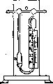
Figure 1. Rheometer with a diaphragm.
liquid: kerosene, water, sulfuric acid, etc. As a general rule, the manometric liquid should not chemically react with the gas passing through the R. When working with air, it is most convenient to use kerosene tinted with alkanin or picric acid. The specific gravity of the kerosene must be definite, since a change in the specific gravity of the liquid changes all calculations. A cardboard scale is attached to one of the knees of the R., on which divisions are marked indicating the quantity of air passing through the R. at one or another position of the manometric liquid. When working with the R., it is necessary to ensure that in the state of rest, the liquid level in both knees of the U-shaped tube exactly corresponds to the zero point of the scale. The practical application of the R. is presented in Fig. 2. By attaching the rheometer to any device, for example, to a Palmer vessel, uniform
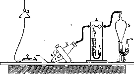
Figure 2. Diagram of rheometer application: 1-electrical fitting with a plug for obtaining electric current; 2-rheostat; 3-electric pump-fan; 4-rheometer; 5-Palmer vessel for trapping dust.
ly suck air through the apparatus; the height of the liquid rise in the R. shows on the scale the volume of air being sucked through per unit of time. This volume, for precise work, should be reduced to 0° and 760 mm of mercury pressure. Rheometers with a diaphragm are used for measuring relatively large quantities of air passing through research apparatus, e.g., from 5 to 150 and more liters per minute; for small quantities of passing air, e.g., in the range of 10-100 cm3 per minute, R. equipped with a capillary instead of a diaphragm are used. Most convenient are R. with removable capillary tubes (Fig. 3), since by changing the capillaries, one can widely vary the speed of the air passing through the R. A disadvantage of the R. with a capillary is its fragility and the easy clogging of the narrow lumen of the capillary with dust and condensed moisture. Therefore, when working with an R. equipped with a capillary, the air or other gas passing through it should be pre-dried and freed from dust. Calibration of rheometers. Often a doubt arises about the accuracy of the R. readings. In such cases, it is necessary to check the correctness of its scale using a gas meter as follows: the R. is attached to a gas meter, as shown in Fig. 4, and air or another gas is sucked through it, maintaining a certain height of the manometric liquid; every minute the readings of the gas meter are noted; the volume of air (or other gas), suck
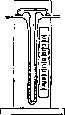
Figure 3. Rheometer with a capillary.
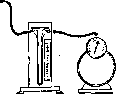
ed in one minute must exactly correspond to the reading of the manometric liquid on the scale of the R. It is sufficient to check three or four points of the scale to judge the correctness of the R. readings and make the corresponding correction to these readings. In order to ensure the constancy of the level of the manometric liquid during the calibration work, a part of the air entering the R. is diverted through a special tube into vessel A, where it exits to the outside in the form of bubbles. By changing the height of the liquid column in vessel A, it is possible to establish an arbitrary difference in the levels of the manometric
liquid in F. Figure 4. Connection of the rheometer
with a gas meter.
liquid in F. Instead of a gas meter for checking the R., one can use calibrated gasometers or large bottles, measuring the quantity of outflowing water per unit of time. The speed of water outflow is regulated by a screw clamp; the bottle must be equipped with a manometer, and during the entire time of water outflow, the liquid level in both ends of the manometer must stand at the same height, since only under these conditions will the quantity of outflowing water exactly correspond to the quantity of air entering it per unit of time. A checked R. can serve as a standard for checking other R. Besides the described types of rheometers, there exist also rheometers of a special design, serving not for measurement, but only for regulating the volume of gas or air passing through research apparatus. These include the Giraud rheometer, the Moitessier apparatus, and others. In laboratory practice, they are usually called gas pressure regulators.
Related articles
Mentioned in
Cite this page
“Rheometers.” Soviet Medical Encyclopedia. English translation of Bolshaya Meditsinskaya Entsiklopediya, 1st ed. (Moscow, 1928–1936), ed. N. A. Semashko. https://sovietmedicalencyclopedia.com/article/reometers/